
Nip loading
Follow nip engagement and release to connect contact load with traction and roller spin-up.
What changes when the pressure roller engages?
What you can model
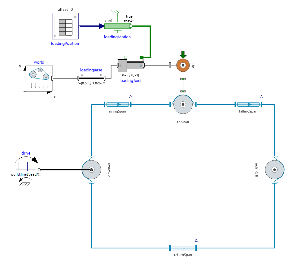
An undriven nip roller moves against a web running over a transport roller. The assembly diagram connects the prescribed nip motion to the contact model. As the nip closes, normal load develops and friction accelerates the roller. The animation follows the same engagement and release sequence.
What you can explore
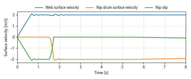
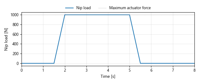
Compare the roller speeds with the applied nip load. The load plot identifies engagement, the holding interval and release; the speed plot shows spin-up and coast-down through those stages. The negative drum speed denotes counter-rotation, while the approaching surface speeds reveal the change in contact slip.
More from Roll2RollDynamics
Misaligned winding line
Explore how a small roller misalignment changes web tracking while span tension remains nearly unchanged.
Explore example →Retracting idler
Explore how idler motion changes web wrap, opens clearance and restores contact during a release cycle.
Explore example →