
Suspension bridge load paths
Trace how a bridge deck, hangers and main cable share gravity loads as the structure settles.
How do cables carry a bridge’s weight?
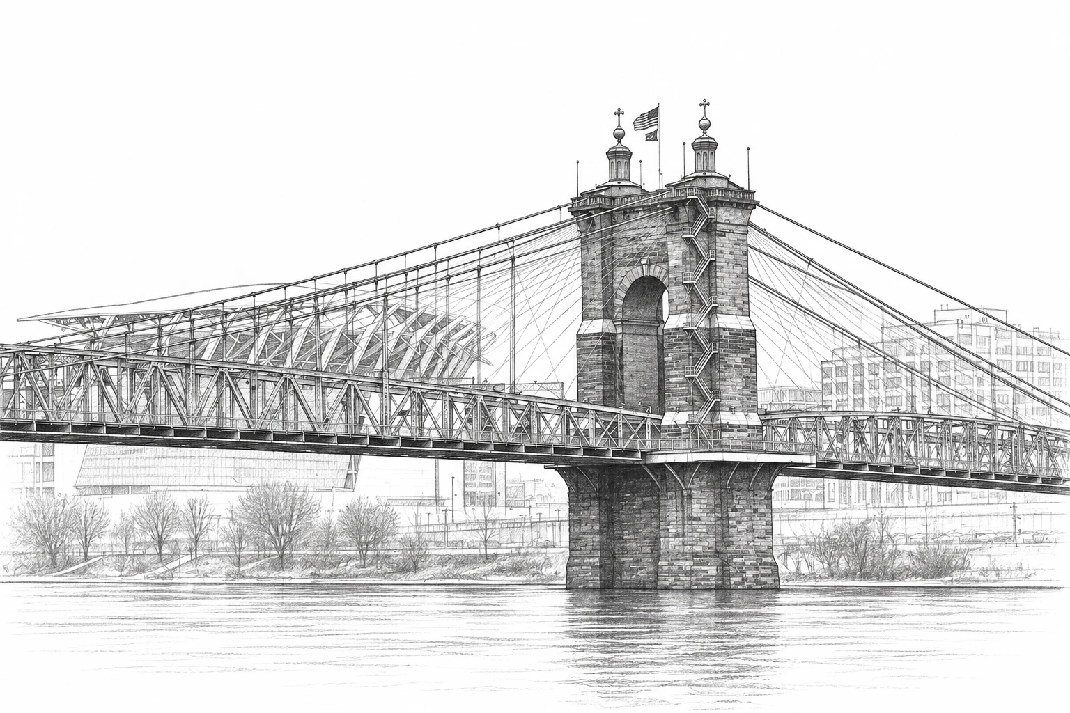
Sketch from photo: Nathaniel Mitchell · Public domain · sketch adaptation
What you can model
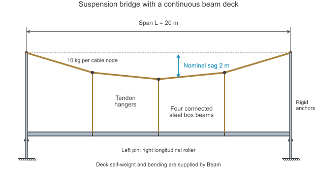
Four connected steel box beams form a continuous deck beneath a segmented main cable. Three vertical hangers transfer load between them, with fixed elevated cable anchorages at the ends. The geometry diagram makes the load path visible before the response plots show the assembly settling under gravity.
What you can explore
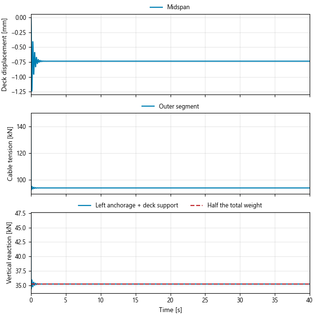
Follow deck displacement and cable tension as the motion approaches equilibrium. Then compare the combined left-end reaction with half the total weight. That reaction includes both the cable anchorage and deck support, showing how their contributions work together to carry the bridge.
More from StructuralMembers
Building on isolation bearings
Separate building sway from foundation travel and examine how an isolation bearing carries the resulting motion.
Explore example →Roof-mounted mass damper
Explore how a roof-mounted mass absorber moves with a building and how much relative travel it needs.
Explore example →