
Caisson production system
Trace separate liquid and gas routes through a caisson, submerged pump and connected production system.
How does subsea inflow reach the surface?
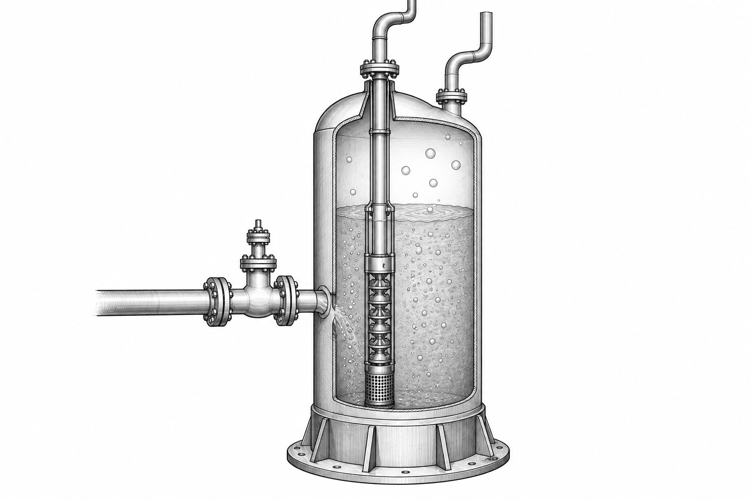
What you can model
The production assembly connects a manifold and flowline to a separating caisson. A submerged electric submersible pump sends liquid through the production riser, while a separate return carries gas to its surface valve. The system diagram shows how these components form one coupled storage-and-pumping model.
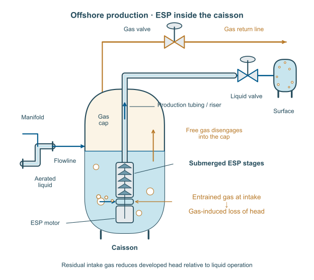
What you can explore
Use the caisson detail to locate the gas cap, aerated liquid column and flow connections. Follow the liquid path toward the submerged pump and the gas path toward the return line. Together, the two diagrams show where separation changes the mixture supplied to the pump.
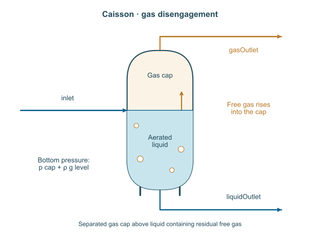
More from OilProductionDynamics
Gas and pump performance
Compare predicted pump pressure rise with published gas–liquid measurements across six steady operating duties.
Explore example →Gas disengagement
Follow gas release after inflow stops and compare the changing liquid-column height with measured shutdown data.
Explore example →