
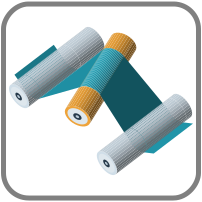
 Roll2RollDynamics is a Modelica library for roll-to-roll web handling. Spans
stretch, rolls slip, nips load and winders change radius, all in one
connected model that also tracks where the web runs across the machine.
This post covers version 1.0.0. We walk through its examples, from a
two-pulley belt drive to a full unwind-to-rewind line, and close with what
the library does not model.
Roll2RollDynamics is a Modelica library for roll-to-roll web handling. Spans
stretch, rolls slip, nips load and winders change radius, all in one
connected model that also tracks where the web runs across the machine.
This post covers version 1.0.0. We walk through its examples, from a
two-pulley belt drive to a full unwind-to-rewind line, and close with what
the library does not model.
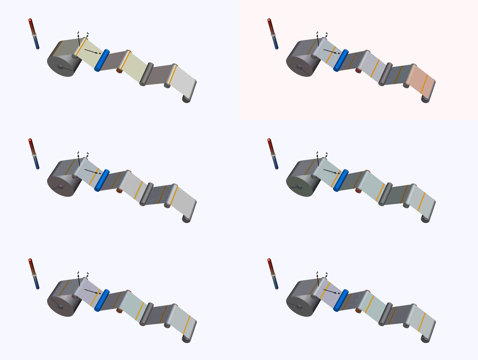
Figure 1. A film line with a dancer and a yawed idler. Wound radii change as the web travels, and colour shows the modeled web stress.
Building the Web Path
How much of a model has to change when a roller moves?
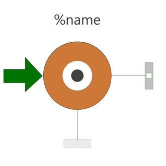
Only the roller's position. Roll positions and radii set the tangency points, span lengths and wrap angles, so the spans follow any roll that moves. Four components build most of a line:
| Belt | Roller | NipRoller | Winder |
|---|---|---|---|
 |
 |
 |
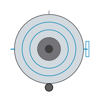 |
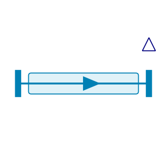
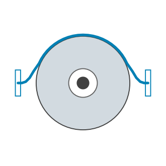
Belt: the free span. Longitudinal inertia, elastic stretch and internal damping, with entry and exit tensions free to differ. It represents film and paper spans as well as belts.Roller: the wrapped roll. Roll inertia and bearing drag, with traction and slip at the contact. The same component serves as a driven roll, an idler or a dancer on a translating joint. With detachment enabled, the web can lift off it.NipRoller: the pressure drum. An undriven drum pressed against web carried by aRoller. Cover compression sets the normal load and friction spins the drum.Winder: the inventory. An unwinder or rewinder whose radius, mass and inertia change as material leaves or arrives.
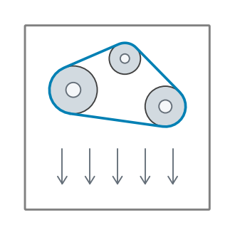
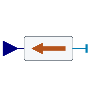
WebWorld supplies material properties and line defaults. WebForce holds
tension at an open end, so a study can cut out part of a line without
modeling the winders.
| WebWorld | WebForce |
|---|---|
 |
 |
The web connectors carry geometry, loads and material transport. Mounts and drives use standard Modelica mechanical connectors, so a dancer is a roller on a prismatic joint and a tension controller drives a Modelica Standard Library source.
Every span, wrap and wound roll accounts for the web mass it holds and the mass crossing its boundaries. In a closed loop the total stays constant. In an open line it changes by inflow minus outflow. The same bookkeeping ties wound inventory to roll radius.
Starting an Undriven Pulley
How long does an idle pulley take to catch the belt?
In OpenBeltDrive, the larger pulley runs at a surface speed of 2 m/s and
the smaller one starts at rest. Web traction accelerates it against its
inertia and bearing drag.
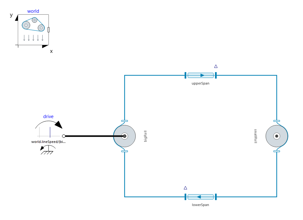
Figure 2. The two-pulley belt drive.
While the pulley slips, traction is capped by friction times belt load. The
preload world.tension therefore sets the ramp. At 75 N, 150 N and 300 N the
pulley reaches 2 m/s after 0.55 s, 0.29 s and 0.16 s. Faster is not free:
overshoot grows from 2.07 to 2.30 m/s.
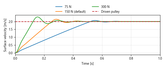
Figure 3. Small pulley startup for three preloads.
Web damping leaves the ramp alone. It decides what happens after the pulley
catches the belt. With world.webDampingTime at 0.001 s the speed rings for
over 2 s and the tension ratio peaks at 2.15, inside the capstan limit of
2.88. At 0.1 s the approach is nearly critically damped.
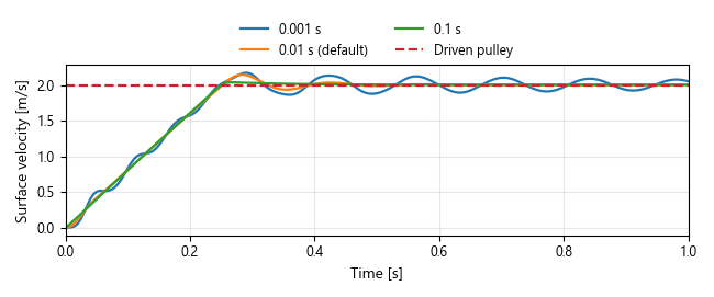
Figure 4. Small pulley startup for three web damping times.
Bearing drag sets the steady state. The driven pulley pulls the lower span,
so the exit side is tight and the entry side slack. Raising
world.bearingDamping from 0.001 to 0.1 N·m·s/rad widens the tight-slack
split from 0.2 N to 23 N, and the tension ratio rises from 1.00 to 1.18.
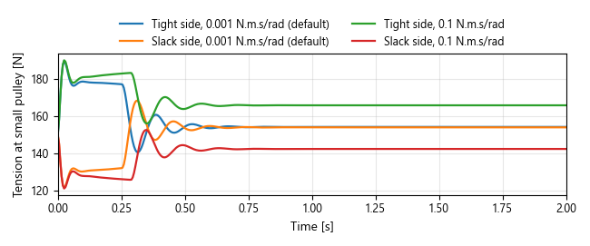
Figure 5. Tight and slack side tensions for two bearing drags.
Loading a Nip
How much traction does closing a nip buy?
NipLoading adds an undriven drum on a loading slide to a three-roll loop.
The slide closes the nip, holds, then releases it.
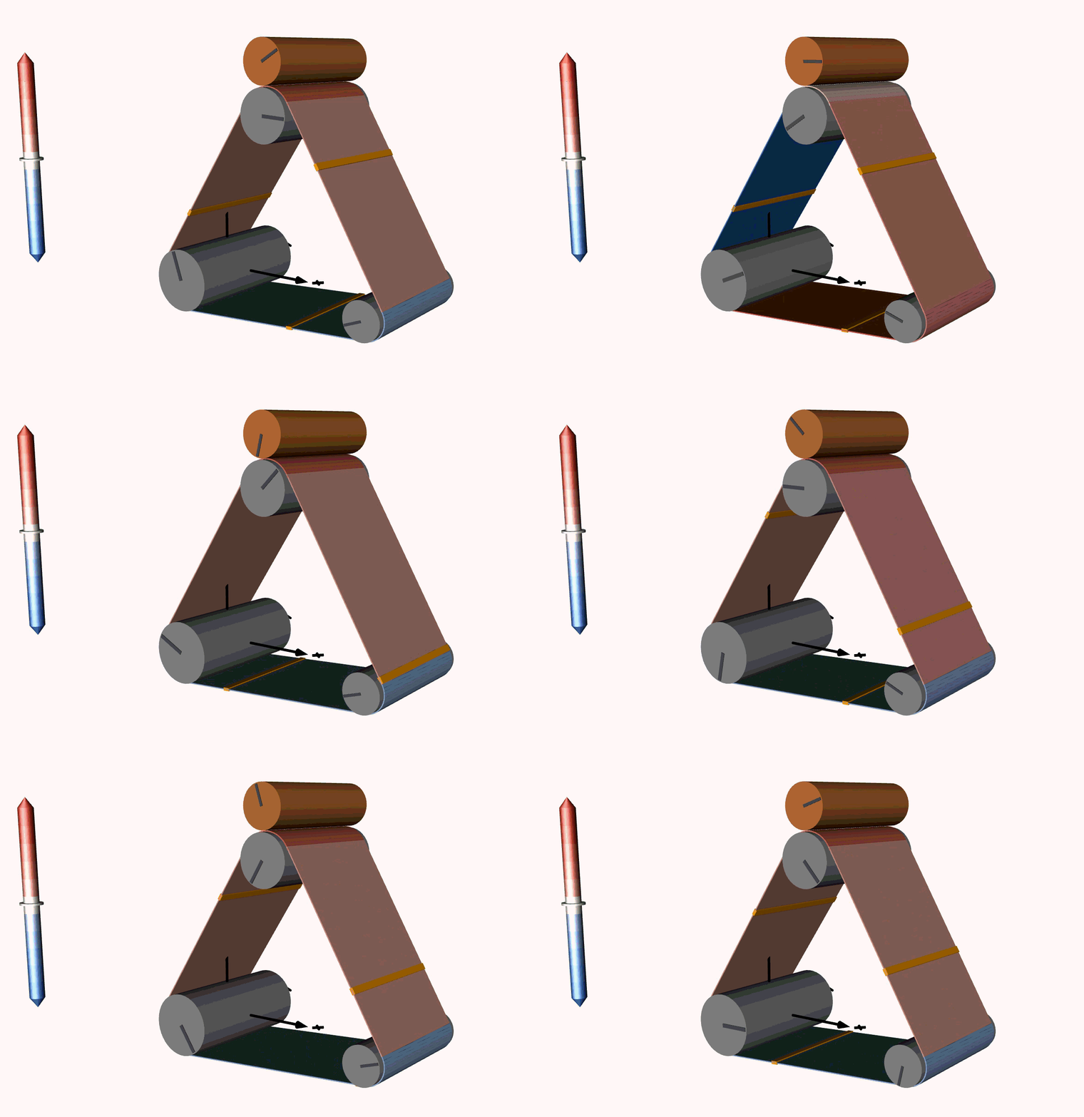
Figure 6. The nip drum closes onto the moving web, spins up through friction, and lifts away as the slide withdraws.
A cover stiffness of 1 MN/m held at 1 mm compression gives 1,000 N of contact load and 350 N of extra traction capacity at the loaded roller. That capacity is headroom. The roller draws on it only when the line demands it.
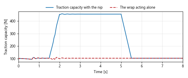
Figure 7. Available traction with and without nip loading.
One modeling trap: the slide prescribes position, so contact force follows
compression and approach velocity. maxNipLoad documents the actuator
rating but does not cap that force. A force-limited actuator has to be
modeled as one.
Real nips are rarely square. A yaw crosses the roll axes, and a tram tilt
wedges one end closed. The contact model integrates the cover law across the
face to get the load and where it acts. SlipAndTractionCapacity isolates
the friction law, sweeping slip velocity with and without the nip.
Engagement moves web between spans and wraps. Does any of it go missing?
Figure 8 tracks both stores through the nip cycle. They move in opposite
directions, and the closed-loop residual massBalanceError stays under the
1 mg acceptance limit.
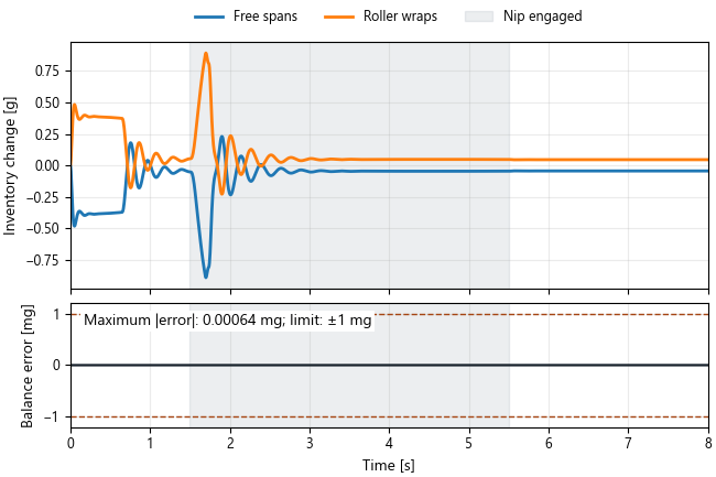
Figure 8. Web redistribution and mass balance during nip loading.
Following Drum Runout
What happens when a drum centre sits slightly off its bearing axis?
The Roller parameter runout sets that offset. As the drum turns, its
centre orbits the bearing axis and the adjoining spans lengthen and shorten.
An idler with 0.3 mm runout on a 2 m/s line produces a tension ripple once
per turn. The motion stays in the web plane, so it does not steer the web.
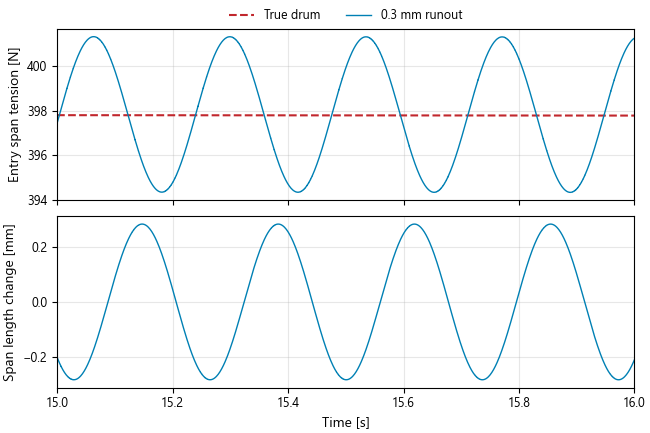
Figure 9. Span tension and length with 0.3 mm idler runout.
Under a nip, runout becomes load ripple. With nip.runout = 0.3e-3, the
held 1,000 N swings between about 700 N and 1,300 N. On an eccentric driven
roll, use a torque drive or a dynamic speed controller so the shaft keeps
its rotational degree of freedom.
Following Lateral Motion
What does a small roller yaw do to the web position?
SheltonSteering runs a one-metre span at 2 m/s into a roller yawed by
0.004 rad. Shelton's first-order law predicts a 4 mm offset with a 0.5 s time
constant. Figure 10 overlays the library and that analytical curve, with the
difference below.

Figure 10. Lateral steering against Shelton's analytical prediction.
The example documentation goes further. Nine published PET-film measurements check how the offset scales with yaw and tension. Shelton's measured frequency response shows where a first-order law stops working: fast lateral oscillation needs span bending, which the library does not model.
MisalignedIdlerLine puts steering and tension control in one machine. The
film line of Figure 1 runs at 2 m/s and 400 N, and its yawed idler settles
the web about 2.23 mm off centre. Registration and tension can be studied
together.
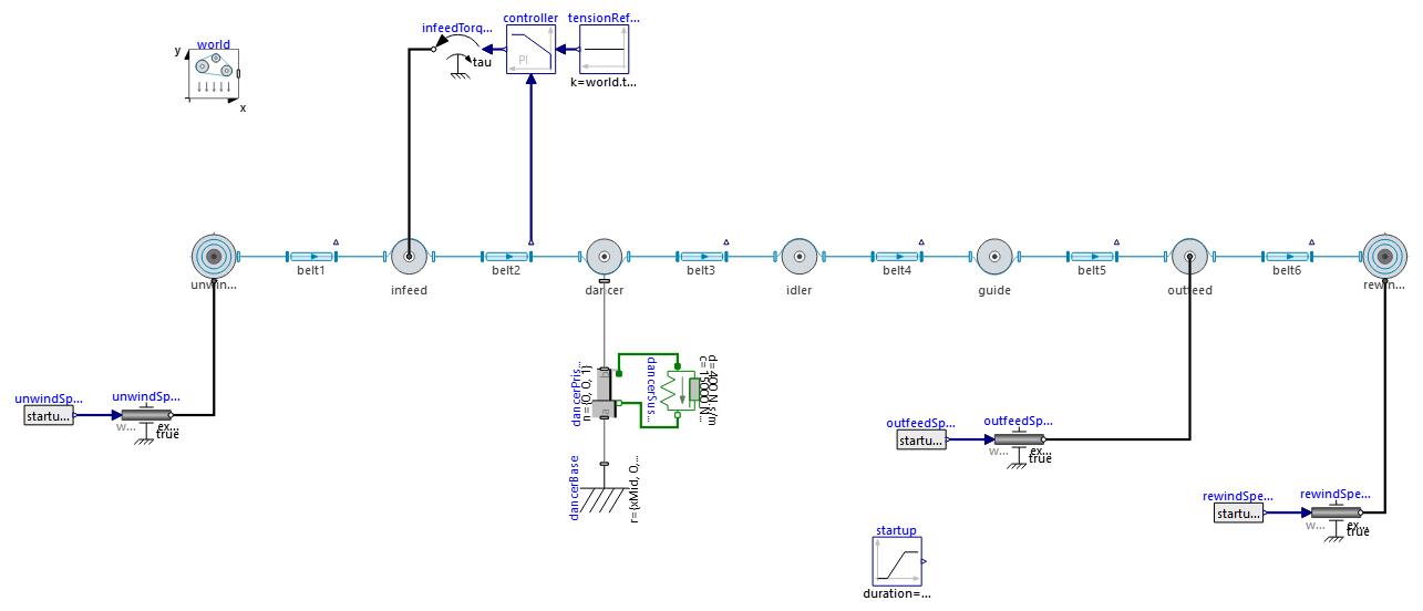
Figure 11. The complete film line and tension controller.
A nip on that line does not cure the tracking. With lateral dynamics enabled, a crossed nip competes with the wrapped roller for control of the web's sideways motion.
Detaching an Idler
A moving roller can leave the web path completely.
In RetractingIdler, a slide lowers an idler until the taut web takes the
direct path between its neighbours, then brings it back. Two WebForce
boundaries keep the ends under tension.
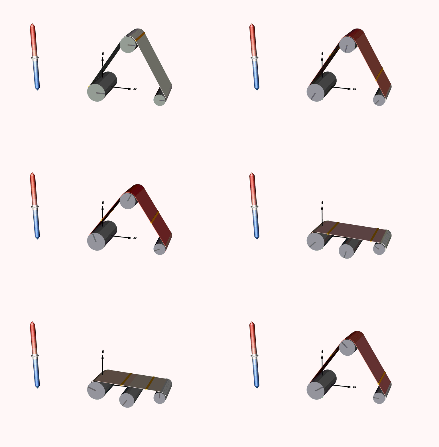
Figure 12. The idler retracts, the web straightens, and contact returns on the upstroke.
What does the idler do while it is clear? It coasts. The web leaves at about 9.4 s and picks it up again at about 15.6 s. In between, bearing drag slows the idler from 1.98 to 1.89 m/s. Tension holds near 150 N, with ±17 N kicks at release and pick-up. The bigger swings where the slide starts and stops come from its prescribed acceleration.
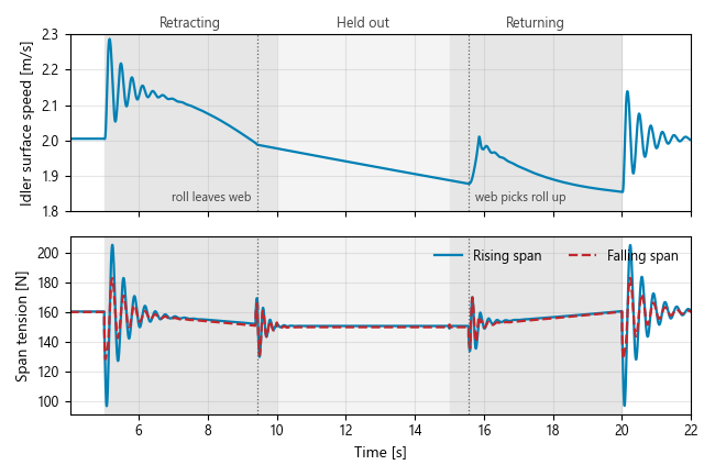
Figure 13. Idler speed and span tension through the stroke.
Validation and Limits
The library's Validation page sorts its evidence into measurement
comparisons, analytical checks and internal consistency.
- Measurements.
KimTwoActuatorLinecouples an unwinder and rewinder through nine spans and compares constant-tension runs at 0.1, 0.2 and 0.3 m/s with published data. Bearing drag is fitted to one reported tension difference. The PET steering data above fit an effective span length. - Analytical. Shelton's first-order steering law, the capstan limit and the friction curve's defining points.
- Runout. The model reproduces the fundamental at the roll's turning rate but not the measured higher harmonics. The absolute amplitude is not independently validated.
- Misaligned nips. Load distribution and crossed-nip steering have consistency and qualitative support only.
The physics has firm edges. The web must stay taut. Spans are straight, with no bending, wrinkling or wave propagation along them. Lateral motion is one offset per roll rather than a cross-width stress field. Rollers can translate, but yaw and tram are fixed for a run. Friction is regularized, so transmitting force needs finite slip.
Roll2RollDynamicsTest holds the regression scenarios and numerical checks.
Getting Started
Load Roll2RollDynamics/package.mo (Modelica Standard Library 4.1.0) and
open Examples.OpenBeltDrive. Halve the preload and watch the ramp stretch.
Then try a stiffer nip cover in NipLoading, or double the yaw in
SheltonSteering.
For a full line, the Getting Started guide builds MisalignedIdlerLine one
component at a time.